Specifying the Chemically Enhanced Backwash (CEB) Mode for UF
This is similar to the specifying the Backwash Mode.
CEB Temperature
WAVE uses the design temperature (specified in the Feed Water Tab) by default for CEB (Figure 1).
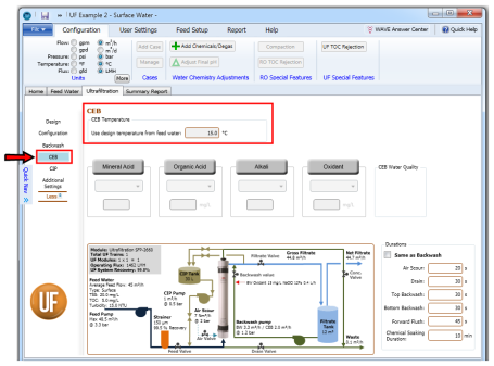
Figure 1: UF CEB specification in WAVE, with default temperature highlighted
Note: Currently the effect of different CEB temperatures on the system design (by affecting density/feed pressure) is not included in WAVE.
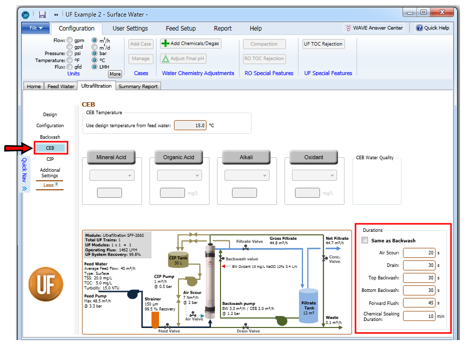
CEB Durations
WAVE populates the durations of the multiple steps within the CEB mode; Air Scour, Drain, Top and Bottom Backwash, Forward Flush by default based on the feed water type and subtype. However, users can also specify their own duration values as shown in Figure 2.
Notes:
- Once the CEB durations are specified to be the same as Backwash durations, any changes in Backwash durations are automatically reflected in CEB durations.
- Changes to the Top or Bottom Backwash durations would affect the operating flux and would be reflected automatically in the UF System Diagram.
- The WAVE user can specify the CEB Flux and how far apart the CEBs are in the Design Window. By modifying the Top and Bottom Backwash durations, the user can effectively modify the amount of water used for Backwash. This would be reflected in the UF system recovery.
- Modifying the Air Scour and Drain durations for CEB would affect the Operating Flux, as these would affect the timing of the UF system.
- Modifying the duration of Forward Flush, with flowrate specified in the Design Window and source specified in the Backwash Window, affects the Operating Flux and System Recovery.
CEB Mineral Acid Selection and Dose Specification
WAVE allows for the addition of a mineral (i.e. inorganic) acid for CEB. This is done by following the steps below (Figure 3):
- Click on the “Mineral Acid” button to activate it. The grey area would turn green. In addition a line feeding CEB Acid to the Backwash line (named CEB Acid) would appear in the UF System Diagram.
- Click on the dropdown arrow.
- Select the mineral acid of interest. The name of the chemical and its concentration in CEB Acid stream would be displayed in the UF System Diagram.
- Specify the target pH for pH reduction in the CEB stream (if the ionic composition of the feed water is available) or target mineral acid concentration in the CEB stream. The target mineral acid concentration in the CEB stream would appear in the UF System Diagram.
-
Click over or tab to move elsewhere in the CEB Window.
Specification of a Mineral Acid for CEB (a) Activating the Mineral Acid option (b) Selecting the Mineral Acid (c) Specifying the target pH or concentration in the CEB stream
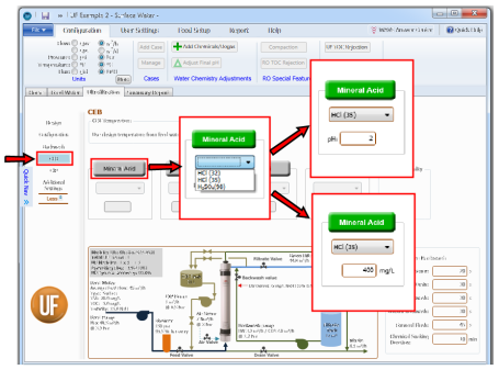
Figure 3: Specification of a Mineral Acid for CEB (a) Activating the Mineral Acid option (b) Selecting the Mineral Acid (c) Specifying the target pH or concentration in the CEB stream
LSI and S&DI Entry during Acid Addition in CEB
If ionic composition is not defined on the feedwater screen, the LSI cell will be blank. Otherwise, if ionic composition is defined, the LSI cell as a pH value is specified (Figure 4). The LSI (Langelier Saturation Index) is an indicator used to determine the need for calcium carbonate scale control. This is important in UF because UF is usually a pretreatment for RO feed. The LSI is applicable for water streams containing up to 10,000 mg/L of total dissolved solids. For water streams containing greater than 10,000 mg/L of total dissolved solids, the Stiff & Davis Stability Index (S&DI) is preferredFigure 6).
Changes in Mineral Acid input in CEB with no Ionic Composition
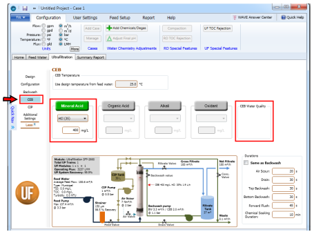
Figure 4: Changes in Mineral Acid input in CEB with no Ionic Composition
Changes in Mineral Acid input in CIP with feed TDS < 10,000 mg/L
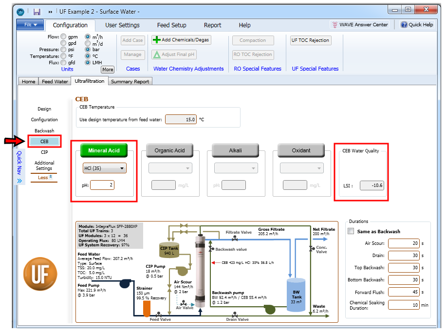
Figure 5: Changes in Mineral Acid input in CIP with feed TDS < 10,000 mg/L
Changes in Mineral Acid input in CIP with feed TDS > 10,000 mg/L
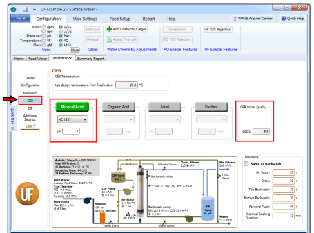
Figure 6: Changes in Mineral Acid input in CIP with feed TDS < 10,000 mg/L
Changes in Alkali input in CIP with feed TDS > 10,000 mg/L
Notes:
- The list of mineral acids is defined by the user as described in Sections Chemical Library and Adding a New Chemical.
- The target pH in the CEB stream for pH reduction (if the ionic composition of the feed water is available) or target mineral acid concentration in the CEB stream interconvert automatically, i.e. if the user initially did not have ionic composition data and entered target mineral acid concentration, but later enters some ionic composition data, the target mineral acid concentration is converted to a corresponding pH and vice versa.
- If the “Mineral Acid” button is activated, WAVE would require selection of a mineral acid and a corresponding pH/target concentration.
- Clicking on the “Mineral Acid” button a second time would deactivate the input cell and remove the CEB Acid line from the UF System Diagram. Setting the target concentration to zero would not remove the CEB Acid line from the UF System Diagram.
CEB Organic Acid Selection and Dose Specification
WAVE allows for the addition of an organic acid for CEB. This is done by following the steps below (Figure 7):
- Click on the “Organic Acid” button to activate it. The grey area would turn green. In addition a line feeding CEB Organic Acid to the Backwash line (named CEB Organic Acid) would appear in the UF System Diagram.
- Click on the dropdown arrow.
- Select the organic acid of interest. The name of the chemical and its concentration in CEB Organic Acid stream would be displayed in the UF System Diagram.
- Specify the target organic acid concentration in the CEB stream. The target mineral acid concentration in the CEB stream would appear in the UF System Diagram.
-
Click over or tab to move elsewhere in the CEB Window.
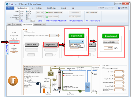
Figure 7: Specification of an Organic Acid for CEB: Activating the Organic Acid option; Selecting the Organic Acid and Specifying the target concentration in the CEB stream
Notes:
- The list of organic acids is defined by the user as described in Sections Chemical Library and Adding a New Chemical.
- If the “Organic Acid” button is activated, WAVE would require selection of an organic acid and a corresponding target concentration.
- Clicking on the “Organic Acid” button a second time would deactivate the input cell and remove the CEB Organic Acid line from the UF System Diagram. Setting the target concentration to zero would not remove the CEB Organic Acid line from the UF System Diagram.
CEB Alkali Selection and Dose Specification
WAVE allows for the addition of an alkali for CEB. This is done by following the steps below (Figure 8):
- Click on the “Alkali” button to activate it. The grey area would turn green. In addition a line feeding CEB Alkali to the Backwash line (named CEB Alkali) would appear in the UF System Diagram.
- Click on the dropdown arrow.
- Select the alkali of interest. The name of the chemical and its concentration in CEB Alkali stream would be displayed in the UF System Diagram.
- Specify the target alkali concentration in the CEB stream. The target alkali concentration in the CEB stream would appear in the UF System Diagram.
-
Click over or tab to move elsewhere in the CEB Window.
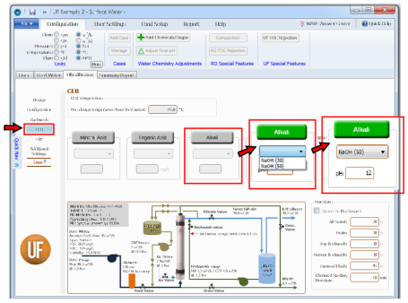
Figure 8: Specification of a Alkali for CEB (a) Activating the Alkali option (b) Selecting the Alkali concentration (c) Specifying the target pH in the CEB stream
LSI and S&DI Entry during Alkali Addition in CEB
One can note the appearance of the LSI cell as a pH value is specified (note the difference between Figure 9 and Figure 10). The LSI is applicable for water streams containing up to 10,000 mg/L of total dissolved solids (Figure 10). For water streams containing greater than 10,000 mg/L of total dissolved solids, the S&DI is preferred (as seen in Figure 12).
CEB Water quality in Alkali input in CEB with feed with no ionic composition
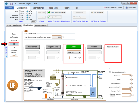
Figure 9: CEB Water quality in Alkali input in CEB with feed with no ionic composition
Changes in Alkali input in CEB with feed TDS < 10.000 mg/L
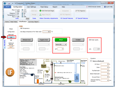
Figure 10: Changes in Alkali input in CEB with feed TDS < 10.000 mg/L
Changes in Alkali input in CIP with feed TDS > 10,000 mg/L
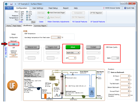
Figure 11: Changes in Alkali input in CIP with feed TDS > 10,000 mg/L
Notes:
- The list of alkali chemicals is defined by the user as described in Sections Chemical Library and Adding a New Chemical.
- The target pH in the CEB stream for pH reduction (if the ionic composition of the feed water is available) or target alkali concentration in the CEB stream interconvert automatically, i.e. if the user initially did not have ionic composition data and entered target alkali concentration, but later enters some ionic composition data, the target alkali concentration is converted to a corresponding pH and vice versa.
- If the “Alkali” button is activated, WAVE would require selection of an alkali and a corresponding pH/target concentration.
- Clicking on the “Alkali” button a second time would deactivate the input cell and remove the CEB Alkali from the UF System Diagram. Setting the target concentration to zero would not remove the CEB Alkali line from the UF System Diagram. (c)
CEB Oxidant Selection and Dose Specification
WAVE allows for the addition of an oxidant for CEB. This is done by following the steps below (Figure 12):
- Click on the “Oxidant” button to activate it. The grey area would turn green. In addition a line feeding CEB oxidant to the Backwash line (named CEB Oxidant) would appear in the UF System Diagram.
- Click on the dropdown arrow.
- Select the oxidant of interest. The name of the oxidant chemical and its concentration in the CEB Oxidant stream would be displayed in the UF System Diagram.
- Specify the target oxidant concentration in the CEB stream. The target oxidant concentration in the CEB stream would appear in the UF System Diagram.
-
Click over or tab to move elsewhere in the CEB Window.
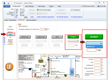
Figure 12: Specification of an Oxidant for CEB (a) Activating the Oxidant option (b) Selecting the Oxidant (c) Specifying the target pH or concentration in the CEB stream
Notes:
- The list of Oxidants is defined by the user as described in Sections Chemical Library and Adding a New Chemical.
- If the “Oxidant” button is activated, WAVE would require selection of an oxidant and a corresponding target concentration.
- Clicking on the “Oxidant” button a second time would deactivate the input cell and remove the CEB Oxidant line from the UF System Diagram. Setting the target concentration to zero would not remove the CEB Oxidant line from the UF System Diagram.