Specifying the Clean-In-Place (CIP) Mode for UF
This is similar to the specifying the Backwash and CEB Modes.
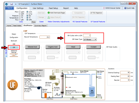
Number of Backwash (BW) steps within a CIP
The most thorough cleaning for a UF module requires the clean in place (CIP) process. The unit operations of a CIP involve:
CIP Source Water
A WAVE user can choose between the following options for CIP water source:
- UF filtrate (product of the UF system being designed in WAVE)
- Pretreated water (water that was passed through the Strainer but not the UF modules)
The choice can be made as shown in Figure 2.
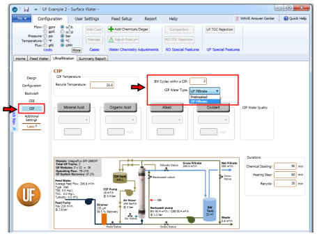
Figure 2: The CIP Water Type specification window for UF modeling in WAVE
Notes:
- The effect of choosing different options for Backwash and Forward Flush would be seen after WAVE completes the UF calculations.
- The default source water for CIP is UF Filtrate.
CIP Recycle Flowrate
CIP chemicals are circulated (recycled) through the UF fibers and housing to clean the system. This flowrate can be specified in the ¨Design¨ window as shown in Figure 4. From the recycle flow rate and duration, the user can calculate the volume of CIP chemicals needed per module.
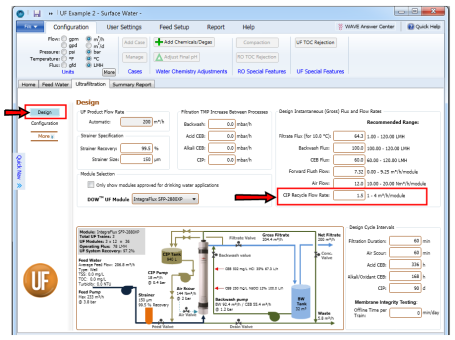
Figure 3: The CIP Recycle Flow Rate modification
Notes:
- 2 m3/h/module is used as the default CIP recycle flowrate in WAVE. It is limited between 1 and 4.
- The effect of changing the CIP recycle flowrate is seen after WAVE models the UF system.
CIP Temperature
The CIP solution can be heated to improve its effectiveness at removing contaminants from the UF membrane. It has the same limits as CEB temperature (1-40°C). It can be specified as shown in Figure 4.
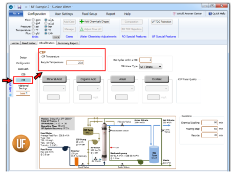
Figure 4: The CIP temperature specification window for UF modeling in WAVE
Note: Currently the effect of different CIP temperatures on the system design (by affecting density/feed pressure) is not included in WAVE.
CIP Durations
Three durations can be defined for CIP in WAVE (as shown in Figure 5):
- Chemical Soaking duration – the amount of time the UF module is soaked in each chemical during CIP
- Heating Step duration – the amount of time taken daily to heat the CIP chemicals from the UF system design temperature up to the CIP temperature ( to calculate energy consumption)
-
CIP Recycle duration – the amount of time during which the CIP solution is circulated through the UF module
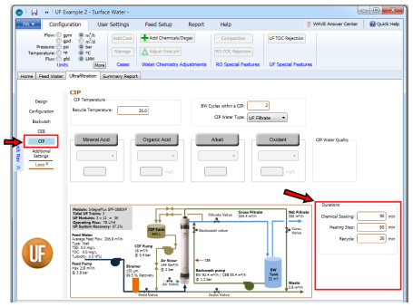
Note: Additional energy will be required to maintain the CIP temperature; however, that is outside the scope of WAVE.
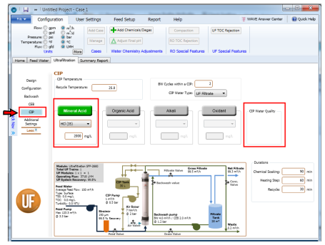
CIP Mineral Acid Selection and Dose Specification
WAVE allows for the addition of a mineral (i.e. inorganic) acid for CIP. This is done by following the steps below (Figure 6):
- Click on the “Mineral Acid” button to activate it. The grey area would turn green.
- Click on the dropdown arrow.
- Select the mineral acid of interest.
- Specify the target pH for pH reduction for CIP (if the ionic composition of the feed water is available) or target mineral acid concentration in the CIP stream.
-
Click over or tab to move elsewhere in the CIP Window.
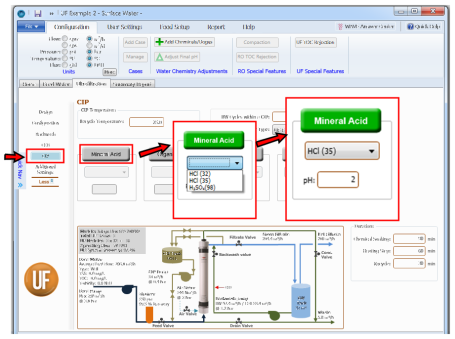
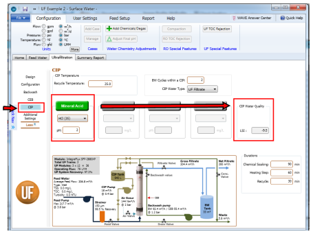
Figure 6: Specification of a Mineral Acid for CIP (a) Activating the Mineral Acid option (b) Selecting the Mineral Acid (c) Specifying the target pH in the CIP stream
LSI and S&DI Entry during Mineral Acid Addition in CIP
The LSI value cell appears as a pH value is specified (note the difference between Figure 7 and Figure 8). The LSI (Langelier Saturation Index) is an indicator used to determine the need for calcium carbonate scale control. The LSI is applicable for water streams containing up to 10,000 mg/L of total dissolved solids (TDS). For water streams containing more than 10,000 mg/L of TDS, the Stiff & Davis Stability Index (S&DI) is preferred (as seen in Figure 9).
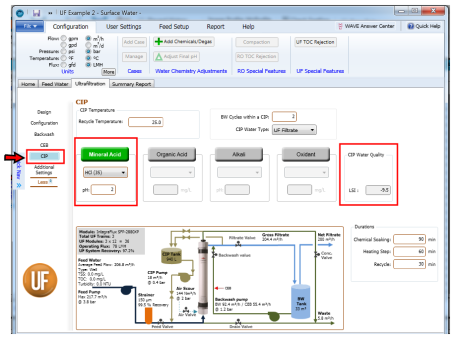
Notes:
- The list of mineral acids is defined by the user as described in Sections Chemical Library and Adding a New Chemical.
- The target pH in the CIP stream for pH reduction (if the ionic composition of the feed water is available) or target mineral acid concentration in the CIP stream interconvert automatically, i.e. if the user initially did not have ionic composition data and entered target mineral acid concentration, but later enters some ionic composition data, the target mineral acid concentration is converted to a corresponding pH and vice versa.
- If the “Mineral Acid” button is activated, WAVE would require selection of a mineral acid and a corresponding pH/target concentration.
- Clicking on the “Mineral Acid” button a second time would deactivate the input cell.
CIP Organic Acid Selection and Dose Specification
WAVE allows for the addition of an organic acid for CIP. This is done by following the steps below (Figure 10):
- Click on the “Organic Acid” button to activate it. The grey area would turn green.
- Click on the dropdown arrow.
- Select the organic acid of interest.
- Specify the target organic acid concentration in the CIP stream.
-
Click over or tab to move elsewhere in the CIP Window.
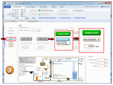
Figure 10: Specification of an Organic Acid for CIP (a) Activating the Organic Acid option (b) Selecting the Organic Acid (c) Specifying the target concentration in the CIP stream
CIP Alkali Selection and Dose Specification
WAVE allows for the addition of an alkali for CIP. This is done by following the steps below (Figure 11):
- Click on the “Alkali” button to activate it. The grey area would turn green
- Click on the dropdown arrow.
- Select the alkali of interest.
- Specify the target alkali concentration in the CIP stream.
-
Click over or tab to move elsewhere in the CIP Window.
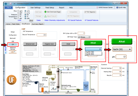
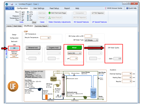
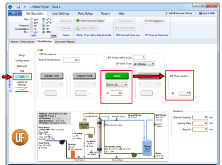
Figure 11: Specification of Alkali for CIP (a) Activating the Alkali option (b) Selecting the Alkali (c) Specifying the target pH in the CIP stream
LSI and S&DI Entry during Alkali Addition in CIP
One can note the appearance of the LSI cell as a pH value is specified (Figure 12 and Figure 13). The LSI is applicable for water streams containing up to 10,000 mg/L of total dissolved solids (Figure 14). For water streams containing greater than 10,000 mg/L of total dissolved solids, the S&DI is preferred (as seen in Figure 14).
Notes:
- The list of alkali chemicals is defined by the user as described in Sections Chemical Library and Adding a New Chemical.
- The target pH in the CIP stream for pH reduction (if the ionic composition of the feed water is available) or target alkali concentration in the CEB stream interconvert automatically, i.e. if the user initially did not have ionic composition data and entered target alkali concentration, but later enters some ionic composition data, the target alkali concentration is converted to a corresponding pH and vice versa.
- If the “Alkali” button is activated, WAVE would require selection of an alkali and a corresponding pH/target concentration.
- Clicking on the “Alkali” button a second time would deactivate the input cell.
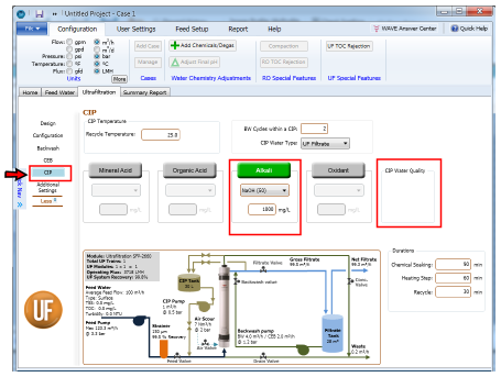
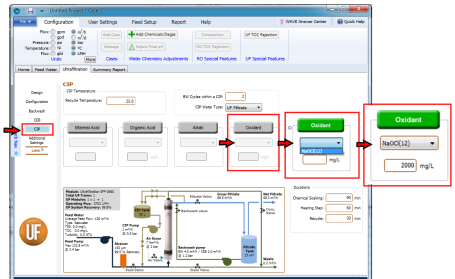
CIP Oxidant Selection and Dose Specification
WAVE allows for the addition of an oxidant for CIP. This is done by following the steps below (Figure 15):
- Click on the “Oxidant” button to activate it. The grey area would turn green.
- Click on the dropdown arrow.
- Select the oxidant of interest.
- Specify the target oxidant concentration in the CIP stream.
-
Click over or tab to move elsewhere in the CIP Window.
UF System Diagram for CIP
The UF System Diagram is displayed in the CIP Window as shown in Figure 4 and Figure 15. Currently, the CIP changes would not be reflected in the UF System Diagram.