The UF Process Flow Diagram
Based on the information provided in the Design and Configuration Windows, WAVE generated the UF process flow diagram as shown in Figure 1. It is shown interchangeably with the Recommended Configurations Table. One can generate the UF System Diagram by clicking on the “Show UF System Diagram” button as shown in Figure 1. The user can restore the Recommended Configurations Table by clicking on the “Show Recommended Configurations” button as shown in Figure 1.
As shown in in Figure 1, The UF System Diagram displays:
- Flowrates (feed, product, Backwash, CIP, air scour, chemicals)
- Feed water composition (TSS, TOC, NTU, SDI)
- Number of skids and modules
- UF module type
- UF system recovery and strainer recovery
-
Tank sizes (Backwash or Backwash + filtrate, CIP)
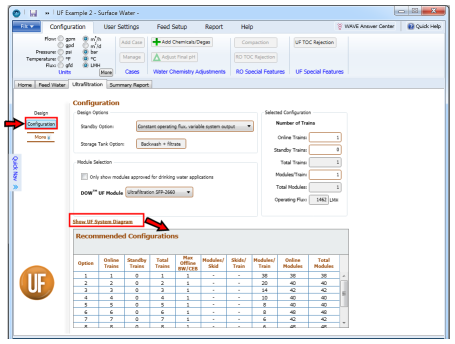

Figure 1: Generating the UF System Diagram restoring the Recommended Configurations Table
Notes:
- Specifications in the Configuration or Design Windows.
- The UF System Diagram can be generated from the Design Window as well as the Configuration Window using the same procedure.
- There would be a CIP Tank even though there may not be a CIP (standby) train.
- When the Backwash (BW), CEB and CIP steps are specified, there would be changes to the UF System Flow Diagram. These are discussed in more detail in upcoming sections.