Additional Inputs – Flow Calculator Window
There are a few additional inputs that may be adjusted to optimize the design. Note the general layout of the window; there are three (3) sections: Pass Average, PF Cycle and CC Cycles. Unlike traditional RO, the feed and permeate varies between the PF and CC mode. The first section is the average of those two modes. For example, the permeate flow rate on average is 100 gpm, while in PF it is 26.11 gpm and 108.80 during CC. The CC permeate flow is higher than the average flow as less water is produced during PF mode (to make up the difference).
The additional inputs include:
- Feed Ratio;
- Recovery;
- Conc. Recycle; and
- Pressure Vessel Size (see Figure 1).
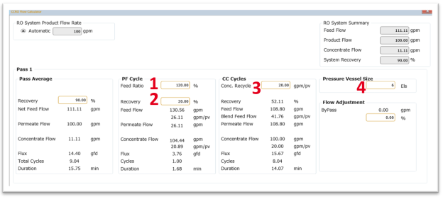
Flow Calculator input notes (see Figure 1):
- Default Feed Ratio of 120%. Recommended range is 110% – 150%.
- Default Recovery of 20%. Recommended range is 10% – 30%.
- Default Conc. Recycle of 20 gpm/pv (4.54 m3/h). Recommended range is 20 – 35 gpm (4.54 – 7.95 m3/h) per PV. Aside: rule of thumb is 10% CC recovery per membrane, 5 elements = 50%.
- Default Pressure Vessel Size of 6 elements (Els), assuming five (5) elements per PV (one more than the # Els per PV). This parameter refers to the length of the PV, independent of how many membranes are installed.
Note: The Flow Calculator calculates and displays a number of helpful calculated values. These calculations enable users to make adjustments on the fly without the need to wait for the more intensive report calculations.
The following section describes the flow calculator inputs in detail and describes different scenarios when those would be adjusted and the reasoning for the adjustments.
-
PF Cycle Feed Ratio is the ratio between the feed flow during PF Mode and CC Mode. In the above example, PF Feed Flow is 130.56 and CC Feed Flow is 108.8. This yields a PF Cycle Feed Ratio of 120% (120% = 130.56 / 108.8). In simpler terms, it is equal to 1.2x the feed flow during CC mode. During CC mode, 100% of the concentrate is recirculated, helping to maintain the design cross flow across the membranes. During PF, the brine is diverted to drain. Without adjustment to the feed flow, the cross flow would decrease. The goal of the Feed Ratio is to increase the PF Feed Flow to maintain similar concentrate flow per PV as CC Mode (above 20 gpm or 4.54 m3/h). In the above example, the default inputs result in similar cross flow values between PF (20.89 gpm/pv) and CC (20.00 gpm/pv). Hence the logic behind the default values.
The recommended Feed Ratio is 110 – 150%. At a Feed Ratio of 100%, the feed flow during CC and PF would equal the average (i.e. all the same). The range of 110 – 150% is recommended to stay within the range of the high pressure pump curve.
- PF Cycle Recovery is the recovery during PF Mode. The default setting is 20%, meaning the permeate flow is equal to 20% of the PF Feed Flow. The low recovery allows for higher cross flow across the membranes. The goal during PF Mode is to flush out the brine as quickly as possible, increasing the recovery would increase the PF time, decreasing the recovery would increase the permeate conductivity through decreased flux.
- CC Cycle Conc. Recycle is the concentrate flow per PV during CC Mode. Since 100% of the brine is recirculated, the concentrate flow rate is equal to the Conc. Recycle multiplied by the number of PVs. The CCRO process is unique in that it decouples flux, recovery and concentrate flow. This allows for Conc. Recycle rate to be entered directly into WAVE. This resolves a common challenge in traditional staged RO designs where it can be challenging to get enough cross flow on tail elements and in the last stage. The circulation pump is sized based on the Conc. Recycle input. The recommended range is 20 – 35 gpm (4.54 – 7.95 m3/h), for both PF and CC Modes. Conc. Recycle flow less than 20 gpm (4.54 m3/h) during CC Mode will display a warning specific to CCRO, while warnings for PF Concentrate Flow follow the FilmTec™ Design guidelines for 8-inch FILMTEC elements in water treatment applications. At low flux, it is more difficult to maintain the PF cross flow; in such cases the input becomes a function of the pump capacity/curve.
- Pressure Vessel Size defaults to one element spacer per PV this helps to increase the volume of the system. One cycle takes approximately two minutes; the exact time for one cycle is the volume of the system divided by the circulation flow rate. Therefore, increasing the volume increases the cycle time. The duration of CC Mode is that time multiplied by the total number of cycles to achieve desired volumetric recovery. CC duration will display a warning if < 5 minutes.