Design Example 1 – Constant PERMEATE Flow Rate
The typical way to design is to allow a decrease in permeate flowrate during PF Mode (to improve cross flow). In a typical system, RO permeate is sent to a product tank or a downstream mixed bed polisher where variable flow is not an issue. Regardless, CCRO may be configured with constant permeate flow rate where the average, PF and CC permeate flow rates are all equal.
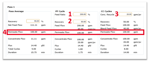
The following are the steps/inputs to create a constant permeate flow rate (see Figure 1):
- Set ‘Feed Ratio’ to 200%. This doubles the flow during PF (which makes up for half the flow lost to drain).
- Set PF ‘Recovery’ to 50%, to match CC recovery.
- Set ‘Conc. Recycle’ of 20 gpm/pv (4.54 m3/h) or adjust until 50% CC recovery is achieved.
- Confirm that permeate flow, average, PF and CC are all equal (ex. 100gpm), since feed flow and recovery are the same during PF and CC (ex. 200 x 50% = 100).
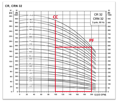
Note: It is important to consider the pump curve/range when doubling the flow during PF. In the above example there are two design points, 100gpm at high pressure and 200gpm at lower pressure. This fits the typical pump profile/curve as head decreases with increasing flow. To illustrate this, see the below sample pump curve, Figure 2. The flow range is 100gpm during CC and 200gpm during PF. At high PF recovery, the pressure during PF Mode will be much higher than a typical design where the flux and recovery is much lower. In most applications, the high pressure pump may be bypassed during PF (this is low pressure and additional boost is not required).